Some Useful Circuits
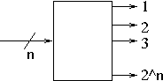
- A decoder is a circuit that given n input lines, selects between 2n output lines.
- Think of it as
- Each of 2n lights is assigned a number.
- If I input the number, light n is lit up.
- Why n and 2n?
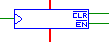
- The normal image is:
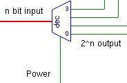
- But in tkgate they have a pwer switch.
- We use a decoder to select among different items.
- Very frequently memory or registers.
- So how would we implement a 3 bit decoder?
- An encoder is the opposite.
- We will use these less frequently, but it is good to know.
- There are 2n input bits.
- And n output bits.
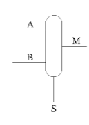
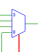
- A multiplexor is a device with
- n data inputs, usually a power of 2.
- 1 control input but it is log2 bits wide.
- 1 data output.
-
-
- Let's build a component of the basic mips architecture.
- MIPS has 32 general purpose registers available.
- This is somewhat of a lie, look at the green sheet.
- Register 0 is just a source for 0, and the bit bucket.
- register 1 is reserved for the assembler.
- Registers 26-31 are reserved for predefined uses
- This is sometimes called the register file.
- For simplicity, let's build a 4 register file.
- This circuit will have one data input and one data output.
- The input will be an 8 bit value to store. (Data)
- The output will be an 8 bit value stored in a register. (Output)
- It will have three control lines.
- A 2 bit output register line, used to select the register for output. (Read Register)
- A 2 bit store register line, used to determine where the data will be stored. (Write Register)
- A clock, which stores the input data when the clock switches from low to high. (clock)
- And two pseudo control lines
- Before we begin, we need a little knowledge of registers.
- Registers have
- A word sized data in line.
- A word sized data out line.
- A clock line.
- An enable not line
- A clear not line.
-
- When the clock goes from low to high, the data on the data in line is stored in the register.
- But the data must be stable on the input line for setup time.
- And nothing must change for hold time.
- The data is available in clock_q time.
- So we will
- Need a decoder to select the register where we will store values
- The Write_Register line will be the input to the decoder.
- Four output lines will, we will and each with the clock input line and feed the individual register clocks.
- This will cause the clock pulse to hit only one register
- Need a mux to select the output
- The four register outputs will be fed as input into the mux.
- The Read_Register line will be used to select the desired register.
-
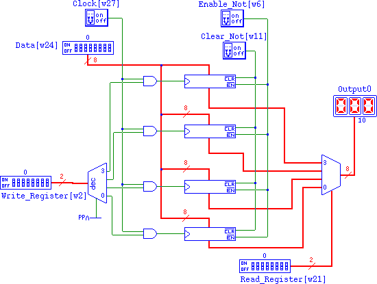
- TKGate implementation