$\require{cancel}$
Introduction
- In this section we will discuss the basics of digital logic.
- We will not become experts, but we will see enough for us to understand the basics of the elements of the CPU.
- I will be refereeing to multiple sources, but An Animated Introduction to Digital Logic Design looks promising.
- This is an open source text.
- I will use chapter 3 and some of chapter 2 for these notes.
- I also plan on using the Digital Simulator
- This is a circuit level simulator.
- It is written in javascript, so you will need to install JRE 8.
- There are instructions for installation.
- I have asked for this software to be installed in the labs as well.
- Some basics.
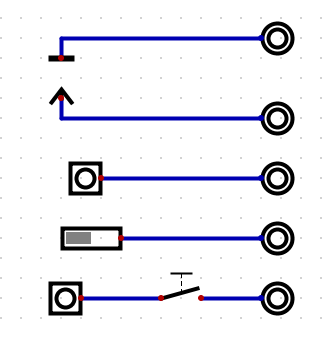
- Under view, I turn on "component view"
- Under wires
- A "Supply Voltage" is a source of positive voltage, think 1
- A "Ground" is a sync for positive voltage, think 0
- Under IO
- "Output" is a way to display a value.
- Output is nice because it displays
- A bright green circle for positive (1)
- A dull green circle for negative (0)
- A gray circle for nothing. (no value)
- "Input" Is a switchable source of a value
- "DIP Switch" is also a source of a value.
- Under Switches
- "Switch" is a normal throw switch.
- On each of these is a dot.
- Red dots are output
- Blue dots are input.
- You can drag wires from one dot to another.
- The nice thing is if you hook it up wrong, the smoke does not escape from the device and make it stop working!
- IE in the simulator, we can't burn up a component.
- Click on one dot and drag the wire to another.
- You can force a turn in the wire once.
- You can force a second turn in the wire by clicking.
- Finish a wire with a right click.
- You can delete a wire by highlighting it and pressing delete.
- Or click on the trash can.
- By the way, there is a tutorial and manual.
- Move items by highlighting and dragging
- If you highlight part of a wire, it will extend.
- If not, the item will move alone.
- Some simple i/o demonstrations
