Multiplexing
- From the start of the chapter:
- To make efficient use of high-speed telecommunications lines, some
form of multiplexing is used. Multiplexing allows several transmission
sources to share a larger transmission capacity. Two common forms
of multiplexing are frequency division multiplexing (FDM) and
time division multiplexing (TDM)
- Frequency division multiplexing can (be) used with analog signals.
A number of signals are carried simultaneously on the same medium by
allocating to each signal a different frequency band. Modulation
equipment is needed to move each signal to the required frequency
band, and multiplexing equipment is needed to combine the modulated
signals.
- Synchronous time division multiplexing can be used with digital
signals or analog signals carrying digital data. In this form of
multiplexing, data from various sources are carried in repetitive
frames. Each frame consists of a set of time slots, and each source
is assigned one or more time slots per frame. The effect is to
interleave bits of data from the various sources.
- Statistical time division multiplexing provides a generally more
efficient service than synchronous TDM for the support of terminals.
With statistical TDM, time slots are not pre-assigned to particular
data sources. Roather, user data are buffered and transmitted as
rapidly as possible using available time slots.
- Intro
- Multiplexing is used on trunk lines.
- Many lower rate connections are collected at a common point
- They all need to be transfered elsewhere
- There is a single fast line (trunk)
- Example:
- Many slow connections from homes to a central office
- One fast line from central office to another central office
- This is called a multiplexing.
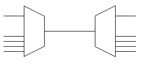
- The device that takes n input lines and produces a single output
signal is called a multiplexer or MUX.
- The device that takes a single input and produces n output signals
is called a demultiplexer or DEMUX.
-

- The difference between this and the view in architecture is
that the line between the two devices can carry all of the data.
- Reasons for multiplexing
- The higher the data rate, the more cost-effective the
transmission facility.
- The cost of the equipment goes down as the throughput goes up
(fill the airplane and you make more money)
- Most communications needs are modest.
- We need to have multiple simultanious connections to
comply with the first point.
(my modem operates up to 56Kbps, but connections
rarely provide over 24Kbps)
- Frequency Division Multiplexing - the Radio/TV
- Frequency Division Multiplexing - the Radio/TV
- Each signal is modulated onto a different carrer frequency
- Carrier frequencies are far enough apart so that there is no
overlap
- A signal consists of a bandwidth, and a frequency that it is
centered on. This is called a channel
- An unused portion of the spectrum called a guard band surrounds
each frequency to prevent interference
- The signal is analog, but the data may be digital.
- Cable TV uses this method
- TV signals fit in a 6MHz bandwidth
- A table in the book shows the bands for each channel (p 240).
- Channel 2 uses 54-60 MHz
- Channel 3 uses 60 - 66 MHz
- Coax can go as high as 500MHz
-

- In general
- n messages, m1 to mn are to be sent
- They are modulated onto carrier f1 to fn
- Each fi is called a subcarrier
- signals s1 through sn are produced.
- These signals are summed to produce mb a baseband signal
- this is then can be modulated to a new frequency fc
- The total bandwidth used by this signal is greater the the sum of the bandwidths of the modulated signals.
- At the receving end, the signal is send through a series of
filters that extract the individual signals.
- FDM has two problems
- If the spectra of the cajacent component signals are not
far enough apart, crosstalk can occur
- It is susceptable to effects of noise due to amplification
and this could have one component effect another.
- The section concludes with a discussion of how AT&T multiplexes
phone lines together.
- Each phone connection requires about 4kHz
- 12 lines are modulated into a group
- frequencies between 60kHz and 108kHz
- This forms a group.
- Groups use about 48kHz of bandwidth (4x12)
- These are collected in sets of 5 to form a supergroup
- This requires a bandwidth of 240 kHz (5 x 48)
- The next step is a Mastergroup (5 supergroups)
- The next step is a Jumbogroup (6 Mastergroups)
- THis has a bandwidth of 17MHz
- Synchronous Time Division Multiplexing (TDM)
- Multiple low datarate signals can be combined into a higher data
rate signal by interleaving the signals
- This can be done at the bit, byte, block or higher level
- Data is organized into frames
- Each frame contains a cycle of time slots
- A sequence of slots are dedicated to each data source
- The sequence for one source is called a channel
- Flow control - just send empty entries in the channel that is going
to fast (We skipped this in 7, but will be back to it)
- Error correction - do this on a per channel basis too.
- In other words, provide a data link level to the channels
- Frames are typicaly marked by an extra bit pattern such as 101010
- Synchronising the various data sources can be a problem:
- Each has a different clock
- Loss of synchronization is possible
- Data streams might not be sending the same size blocks
- Solution: fill in with extra bits
- This is called pulse stuffing
- Two examples are given of how TDM is used by long distance carriers
- ISDN
- BRI - Basic Interface
- 1 = no voltage, 0 alternates between +750mV and -750mV
- Datarate is 192 kbps
- Two 64Kbps B channels
- User data channels
- For digital data
- For pcm phone data
- Or other traffic
- Established on a connection basis
- one 16-kbps D channel
- control information
- Lower rate data transmission
- A frame
- 48 bits long
- 1 frame every 250usec
- 192kb/sec X 1 frame /48 bits = 4 k frames/sec
- 1 sec/ 4X10³ frames X 1X10⁶ usec/sec = .25x103 frames/sec = 1 frame/250usec
- These frames are set from Terminal Equipment (TE) on the users side
- And from the Network (NT)
- Frames each direction are different.
- NT-TE
- Starts with a framing bit +750Mv
- Low bit (-750Mv)
- 8 bits from B1
- Low bit
- D bit
- Low Bit
- Framing Bit
- Low Bit
- 8 bits from B2
- Low bit
- D bit
- Low Bit
- 8 bits from B1
- Low bit
- D bit
- Low Bit
- 8 bits from B2
- Low bit
- D bit
- Low Bit
- NT-TE frammes are similar
- Execpt D bits are echoed back (for use later)
- Some additional control bits are sent
- A bits are used to activate or deactivate a TE
- Multiple devices can share the d line
- LAPD runs on the incoming channel, so this handles
addressing this direction
- Contention for outgoing bits are resolved using the E
bits (echo above)
- when there is nothing to send, they send 1s (no voltage)
- To transmit
- Listen to the incoming echo bits
- If you receive sufficient to reach a threshold, begin
transmitting
- Listen to echo, if they don't match, collision, stop
and listen for a prescribed period based on your
threshold.
- PRI - Primary Interface
- 1.422 Mbps (T-1, USA)
- 8000 frames per second 125us per frame
- Each Channel 64Kbps
- Multiplexes Multiple channels (23B + 1 D)
- 2.048 Mbps (Europe)
- Read the SONET stuff on page 254-255
- Statistical Time Division Multiplexing
- Consider a network of terminals
- We can assume that most are not sending/receiving data so
- Most of the slots are unused
- n inputs
- k channels
- n > k
- Encode an address, length, and data within a frame for each
source that is ready to send.
- Thus more devices can be supported than using synchronous TDM
- Please read the section on ASDL pages 264-269

