Some notes from chapter 1.
- Images
- In the "real world" we have a single "viewer"
- This is the position where the image is formed.
- Think of this as a camera or your eye.
- We also have multiple physical objects
- In the graphics world, we replace the objects with
- Triangles - as often as we can,
- Vertices
- A line consists of two of these.
- A circle one of these and a diameter
- We generally employ a graphics pipeline to transform from the "vertex" description of the scene to the picture on the screen.
- Our current project somewhat violates that
- We are thinking less of modeling the image than we art of "painting" it.
- Do we have the ability to look from other locations?
- Zoom in?
- We will need to separate the model from the display, but that is about it.
- Light and Images
- In the real world light sources are actual sources of light.
- Either natural or artificial they have a position.
- And they emit photons (light) that strike the objects illuminating them.
- Light is then "blocked" and does not illuminate the items behind the first object.
- Or light is a wave
- These waves are at different frequencies.
- The frequencies correspond to the "color" of light.
- Which corresponds to part of the color that is used to illuminate the object.
- In either case, it is useful to think of what we see of the object is the light that is "bounced off" of the object.
- A stealth object absorbs all light that strikes it.
- Thus there is nothing to see.
- A red object absorb es all but the red light, which bounces off.
- In the graphics world
- We need to model this entire process.
- Lights are assigned properties such as
- Color emitted
- Strength or attenuation
- Possibly direction
- We need to "model" how this light interacts with surfaces
- Does the light reach the surface or is is blocked by another surface?
- Is the light reflected from the surface?
- Is the light transmitted through the surface?
- One way to think of this is pictured in figure 1.11 p 14.
- This is not a practical approach, there are infinitely many rays coming from from the light source.
- But the inverse of the picture, ray tracing
- Another technique radiosity which models a heat transfer technique.
- Traditional rendering
- At each pixel compute the color contributed from each light source.
- This makes shadows and reflections problematic.
- But is reasonably fast.
- Imaging systems.
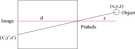
- Consider a pin hole camera
- A box with a very small (pin hole) in one end.
- This is so small only a single ray of light can "travel" through it.
- A photographic plate is on the other end.
- In this case we assume that light is "emitted" from objects in the scene.
- Light travels from the object, through the hole and strikes the plate.
-

- Important here
- The distance d to the image is fixed in the camera.
- The object location (x,y,z) is fixed as well.
- In the image we are looking along the x axis.
- As we move the object, we find distant objects "move" to the center.
-

- in any case, we can compute the point (x',y',z') using geometry
- This point is called the projection point
- (x,y,z) -> (-x/(z/d), -y/(z/d), -d)
- Several definitions
- θ = 2 tan-1(h/(2d))
- This defines the field of view for the camera
-

- This is some way defines the view frustum , With no front plane.
- Or a view pyramid.
- Later we will define a front clipping plane
- This camera has infinate "depth of field"
- Later we will define a back plane, to have a true veiw frustum
- This camera has no adjustments
- We will look at other camera models where this is addresed.
- And we can do all kinds of cool things digitally to mess with the image as well.
- Generally we work with a camera with a focal plane in front of the camera.


