State Machine
- First remember, we have a number of control lines in the devices that
we have been building
- We want to come up with a way to implement the machine
- We will take a clue from the PC to do this
- What does the PC do for the machine?
- Don't we need to do something along the same lines?
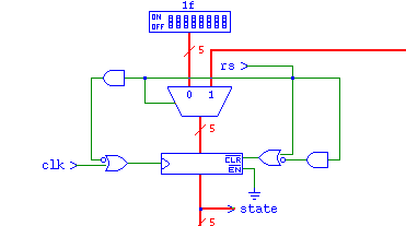
- Inside the control unit, we will keep a register that holds the "state" of the machine
- We always start in state 0
- What are the first three things we do?
- MAR <- PC
- PC <- PC + 1
- MBR <- M[MAR]
- IR <- MBR
- This is essentially the fetch part of the F-D-E cycle
- Just how do we accomplish this?
- MAR <- PC
- PC <- PC + 1
- MBR <- M[MAR]
- IR <- MBR
- Note, that at each step, we really need to just set the proper
control lines.
- Also note, some of these steps can be combined
- After the pc is placed on the bus, we can increment the pc
- And some can't
- We can only do one thing with the bus at a time
- We might have things that take a long time
-
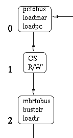
- Each number will reflect a state of the machine.
- At each state we know what next state to go into
- We also know what to do (ie which control lines to lite)
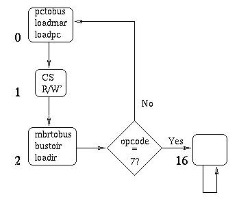
- IF we wanted a fetch only computer, state two could loop back to state 0
- An easy addition,
- Halt
- From state 2 go to state 16
- Stay in state 16.
-
- The next three are special cases just like halt
- skipcond - state 15
- jmpx - state 14
- clear - state 10
- We check the op-code for each
- We have a 1 state for moving data
- Each of these return to state 0 when done
-
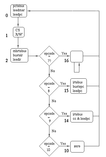
- We have actually covered the odd ball cases here.
We will look at the other cases in the next section
Using the State Machine
- At each state, we know what control lines we wish to light
- So inside the control unit we can build some logic to do this
- If we store the state in a register
- We can detect the state with a mux
- And have a line lit for each state.
- Consider state 10
- It has one action, light the zero line
-

- State 16 has no actions at this level
- State 14 and 15 do much the same thing.
- 14 JMPX PC <- IR0-11
- 15 Skipcond (increment pc based on IR10-11)
- Both move the instruction register to the bus
- Both (might) load PC
- In 15, only if the CC is a 1.
- 14 we transfer the bus to the PC, in 15 we increment the pc.
-

- Notice there are some delays here to generate the signal at
the right time.
- There are also some lines from other states.
- State 0 wants to load the pc
- State 1 has a special consideration
- We can't move assume that memory is done in a single clock cycle
- So we need to check to see if MD is lit before we proceed
to light loadmbr
- This happens in any memory access state
- Going to the next state
- State 0 always goest to state 1
- State 1 goes to state 2 md is lit
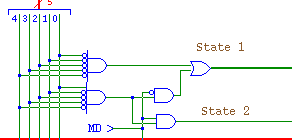
- State 2 must check the 4 bits of the opcode to decide where to go next.
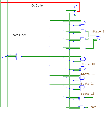
- The output lines go to a Encoder (to produce the next state)
- At the beginning of each clock pulse, we load the next state
- Or 1f (non-state) if we reset the machine.
-
