Just a few more notes from Chapter 2
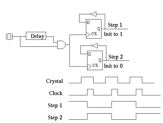
- In the previous section, we saw a circuit with a feedback loop, and
a clock circuit with a delay loop.
- We can combine these to build the control circuitry for our
three number adding machine.
-

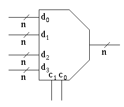
- Just because they are important, describe an N control line mux.
- We will need a slightly modified version of a simple mux.
-

- We will use this in the next chapter.
- Using this mux, how could we improve our design to make it
more generic?
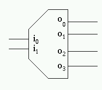
- We will also need another component, an encoder,and a decoder.
- A Decoder takes n inputs and produces 2n outputs.
- It essentially takes an address as input, places a 1 on
the corresponding output line, while changing all other
output lines to 0.
-

| i0 | i1 | o0 |
o1 | o2 | o3 |
|---|
| 0 | 0 | 1 | 0 | 0 | 0 |
| 0 | 1 | 0 | 1 | 0 | 0 |
| 1 | 0 | 0 | 0 | 1 | 0 |
| 1 | 1 | 0 | 0 | 0 | 1 |
- Note, these are just the minterms for an n input circuit.
- We will use this in chapter 3 to construct memory.
- An encoder works the other way, looks at which line is lit and
returns its address.


