Building the Wombat Architecture
- Our goal is to get some idea of what the clock speed of wombat would be.
- We will use the components of TKGate for our standard.
- The components in TKGate
- A register has the following characteristics
- Data Setup 10
- Data hold 10
- Change in clock until data is available 20
- There is an Adder component:
- Look at characteristics
- The "Longest Path" is 70
- The adder has the following ports
- inputs A, B (A+B)
- input carry in
- Output sum
- Output carry out.
- Notice there are also Multipliers and Dividers
- Why no subtractor?
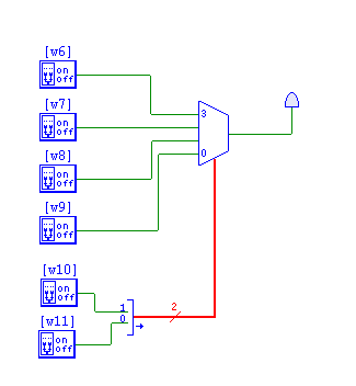
- A Multiplexor
- This circuit lets us select between multiple inputs
- If we have two inputs, we need a single control line to select the output
- If we have 4 inputs, we need two control lines to select the output
- If we have 2n inputs, we need n control lines to select the output.
-
 , and muxA.v
- There are others, but this will do for now.
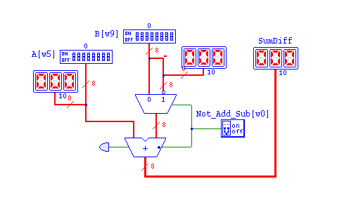
- Could we build a circuit that adds and subtracts using these components?
- Inputs and Outputs?
- Control Lines?
- How do we implement this?
- For now, we will just use +/- in our speed computations for the ALU
- alu.v
-

- How could we build a program counter?
- Let's take a software design approach
- What does the PC need to do?
- What are the inputs?
- What are the outputs?
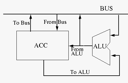
- The ALU and ACC on wombat have a special relationship
- This is semester dependent, so notes might differ, and the simulation might differ as well.
- For all ALU operations, the ACC supplies the second operand.
- So there is a direct connection from the ACC to the ALU
- For most operations, the output of the ALU goes to the ACC
- So there is a direct connection from the ALU to the ACC
-

- The IR is trivial.
- The MMU
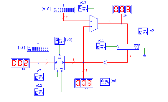
- Memory has the following controls
- An n bit address line (A)
- An n bit data line (D)
- cs
- Chip select
- When this is disabled the memory is active.
- Similar to the clock in a register.
- we
- Write Enable
- When low, write the data on the D line to the memory location specified on the A line.
- When low, a write will occur
- oe
- output enable.
- When low, read the data from the memory location associated with the A line and place it on the D line.
- A memory demo circuit.
-

- To read memory
- Place an address on the address line
- Hold for Daddr_setup
- disable oe
- wait Daddr_hold
- disable cs
- wait Dread
- The output should be produced on the D line.
- Enable cs then oe
- To write to memory
- Place the address on the A line
- Place the data on the D line
- Wait D_addr_setup
- Disable we
- Wait Ddata_hold
- Disable cs
- Wait Dwrite
- Enable cs then we
 , and muxA.v


