Building the ALU Control
- This material is from Chapter 4 as well as from Appendix D.
- We saw that the MIPS alu can be controled by four input lines
| ALU Control | Function |
|---|
| 0000 | And |
| 0001 | Or |
| 0010 | add |
| 0110 | subtract |
| 0111 | slt |
| 1100 | nor |
- This is only part of the instuction set, but will do for our example.
- The control unit will send the following signals to the ALU control
| Opcode | ALUOP |
|---|
| LW/SW | 00 |
| Beq | 01 |
| R-TYPE | 10 |
- Do LW and SW need the same computation?
- Are all R-type instructions created equal?
- How can we tell R-type instructions apart?
- They build the following table, where X means "don't care"
-
| Instruction | ALUOp | FNCTL | ALU Action | ALU Control |
|---|
| LW/SW | 00 | - | add | 0010 |
| BEQ | 01 | - | subtract | 0110 |
| add | 10 | 10 0000 | add | 0010 |
| subtract | 10 | 10 0010 | subtract | 0110 |
| AND | 10 | 10 0100 | and | 0000 |
| OR | 10 | 10 0101 | or | 0001 |
| SLT | 10 | 10 1010 | slt (subtract+) | 0111 |
- Notice
- The first two bits for fnctl don't matter. They are always 10
- So the table can be simplified
| ALUOp1 | ALOOp0 | F3 | F2 | F1 | F0 | Operation |
|---|
| 0 | 0 | X | X | X | X | 0010 |
| 0 | 1 | X | X | X | X | 0110 |
| 1 | X | 0 | 0 | 0 | 0 | 0010 |
| 1 | X | 0 | 0 | 1 | 0 | 0110 |
| 1 | X | 0 | 1 | 0 | 0 | 0000 |
| 1 | X | 0 | 1 | 0 | 1 | 0001 |
| 1 | X | 1 | 0 | 1 | 0 | 0111 |
- They note, that many other combinations are possible, but we don't care as they are not valid.
- As we add more instructions we will have to extend the following.
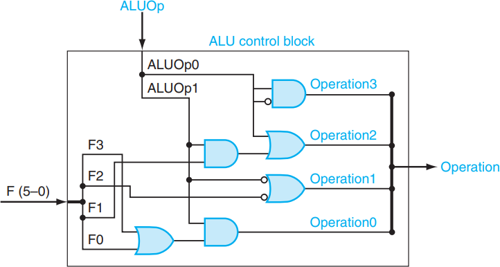
- But look at bit 0 of the Operation.
- It is only 1 when ALUOp1 is a 1 and either F0 or F3 are a 1.
- Or O0 = (F0+F3)ALUOp1
- Bit 1: not F2 or not ALUOp1
- Bit 2: F1 and ALUOp1 or ALUOp0
- Bit 3 is always 0.
- So they provide the following circuit