An ALU for MIPS
- Let's begin by looking at the green card to find the instructions that need the ALU.
- The green card contains only a "core" instruction set.
- Integer only, we are not worried about fp (yet)
- But we may need to worry about the pseudo-instructions
- A more complete set is in appendix A, section 10
- Looking over the list I see the following math instructions
- add, addi, addiu, addu
- and, andi
- nor
- or
- ori
- sub, subu
- For now, we can ignore the u instructions,
- And there is no difference between add and addi for the ALU
- So the list is add, sub, and, or, nor
- But a closer look gives us a few more
- slt and slti both need the ALU to do a comparison
- slt dest, src1, src2
- If the src1 is less than src2, the result is a 1, otherwise a 0
- This can be done with a subtract and look at the resulting MSB
- as does BEQ and BNE
- This can be done by checking to see if the output of the ALU is 0.
- So in addition to the previous list, we need a equal operator.
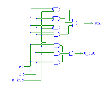
- The general approach is to build a series of 1 bit ALU units and hook them together as you do building a ripple-carry adder.
- In order to match the architecture of MIPS, we will follow their construction technique.
- Looking at the diagram on page 265, we see the ALU has
- Two word sized inputs (32 bits)
- A word sized output
- A 1 bit zero line (true if the output is zero)
- A 4 bit ALU control line
- The important part is to match the operations with the 4 bit control line
- The control line is, for some strange reason (See page B-36)
-
| ALU Control | Function |
|---|
| 0000 | AND |
| 0001 | OR |
| 0010 | add |
| 0110 | subtract |
| 0111 | Set on Less Than |
| 1100 | NOR |
| 0000 | AND |
- The last two digits control a 4 input mux.
- Start by building a circuit that
- Takes two one bit inputs, a and b
- A two bit control line.
- Outputs a·b if the line is 00
- Outputs a + b if the line is 01
- It looks something like this
-

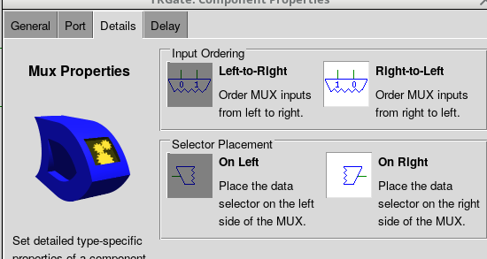
- By the way, you might want to change the default mux orientation
-
- Next build a full adder
- You should have looked at this in 125.
- You will look at this in homework 5.
- And you should read about it on pages B-26 through B-29.
- But you can just take on faith
- Three inputs: a,b, CarryIn
- Two outputs sum, CarryOut
- sum =
a·b·CarryIn
+a·b·CarryIn
+a·b·CarryIn
+a·b·CarryIn
- CarryOut = a · CarryIn + b · CarrayIn + a · b
-
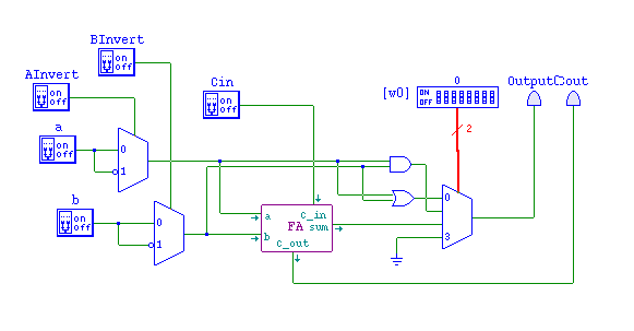
- Hook this full adder in to input 2 of the mux
-
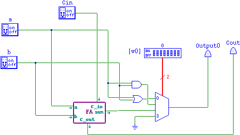
- Note the new input: Cin
- And a new output: Cout.
- Observe that subtraction in two's compliment can be accomplished by
- Flipping the bits and adding 1.
- Which is just running the second bit through a not gate.
- And making the carry in a 1 to the first 1 bit ALU
- So we need another input, BInvert
- Note that this can be driven by the second bit of the aluop.
-
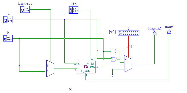
- Finally, we need a nor.
- But De Morgan comes to our rescue here
- a + b = a · b
- Add a AInvert line, this is the msb of the control code.
- feed the output of both multiplexors to athe and/or, we get a nand for free, what is the control code necessary to accomplish this? .
-
- The implementation file.