The Basics of digital logic
- Two terms
- Combinational logic is a system with no memory/ feedback.
- A full adder is an example of combinational logic circuit.
- Sequential logic is a system with memory/feedback.
- A register is an example of a sequential logic circuit.
- I care that you can represent digital logic items three ways
- As a truth table.
- In my experience we design the truth table first.
- As a boolean expression.
- In my experience, we use boolean expressions to simplify the logic produced by the truth table.
- As a circuit.
- This is the ultimate goal of this section.
- Do this for and, or and not.
- A+B for or
- juxtaposition (AB)or · (A·B) for and
- A for not
- Some rules you need to know
- A · 0 = 0, A·1 = A
- A + 1 = 1, A + 0 = A
- A + A = 1, A · A = 0
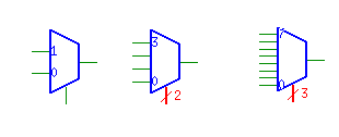
- A multiplexer is a standard circuit which
- has 2n input lines
- has 1 output line
- has n control lines.
- The data on the n control lines select the single input line which will be transmitted on the output line.
- The simplest case is a 2 input (I0, I1), 1 control (C) and one output (O) mux.
-
- Using the above boolean expressions, we can and each input line with the control line to produce something that either passes the data through or a 0.
- Then we can or all of the results together, and only the data will be passed through.
-
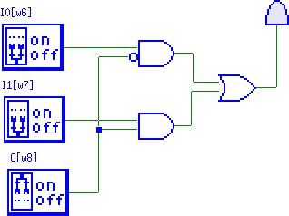
- And this really becomes O = (C · I1) + (C · I0)
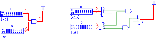
- In general, we can add input ports to and and or gates.
- A·B·C = (A·B)·C = A·(B·C)
- There is a small problem eventually with power being diminished
- But we are not worried about that.
- Just "right click, add port"
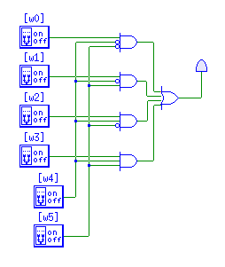
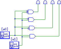
- So I can build a 4 input, 2 control line, one output mux
- The other thing we do in TKgate is build a "wide" version of the gates.
- Just select instance properties and then edit the port widths.
-
- source code
- Muxes
- Are things you can buy on a chip.
- Components→ MSI → select correct mux.
-
- We will use muxes in our construction of the MIPS machine, see for example the future at the top of page 263.
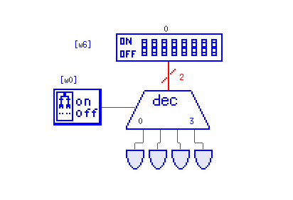
- Decoders
- A decoder has n input lines and 2n output lines.
- A decoder will take an address, on the input, and select a correspondign output.
- For example a 1-4 decoder has 2 inputs and 4 outputs.
| I1 | I0 | O3 | O2 | O1 | O0 |
|---|
| 0 | 0 | 0 | 0 | 0 | 1 |
| 0 | 1 | 0 | 0 | 1 | 0 |
| 1 | 0 | 0 | 1 | 0 | 0 |
| 1 | 1 | 1 | 0 | 0 | 0 |
- The control for this is much like the control for the MUX
-
- source code
- In TKgate the decoder has an extra control line.
- This is a enable/disable line
- This can be set to high
-
- We will use decoders in the construction of the register file.