A TKGate Lab Exercise
We wish to apply the idea of "Using Abstraction to Simplify Design" in our
exercises building items in TKGate. To do this we need to understand how to build modules. This exercise will walk you through this task.
In this project, you will build an 8 bit ripple carry adder. This is based on the discussion in "Computer Science Illuminated, 6th Edition".
- Start TK-Gate, start a new project (Adder.v).
- Place a comment in your document
- Right click in the document, select the components sub menu and the comment choice
-
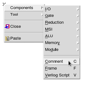
- I will note this as components->comment
- Or left click on the canvas and type C
- Include:
- Your name
- Any collaborators.
-
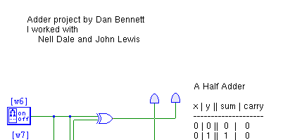
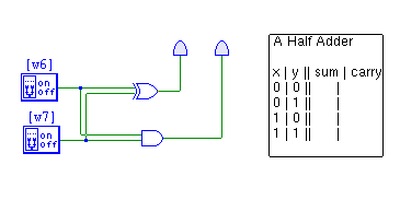
- In the last homework, you built a half adder using gates. Just to review:
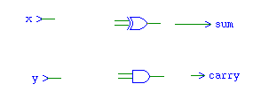
- A half adder computes the sum and carry when two bits are added.
- For inputs x and y, implement the following formulas
- sum = x ⊕ y
- carry = xy
- (⊕ is the exclusive or (xor) operator)
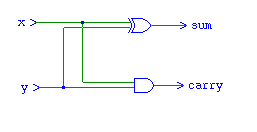
- Develop this circuit. We will use it to test the module once we have it built.
- In a comment, record the truth table for this circuit. (You will need to derive this from the equations or from running the circuit)
-
- In tkgate you can build a module, or hardware component.
- Build a half adder module.
- Select Module, New from the main menu.
- Enter the title of your module into the Name and select ok. Name this module HA for half adder
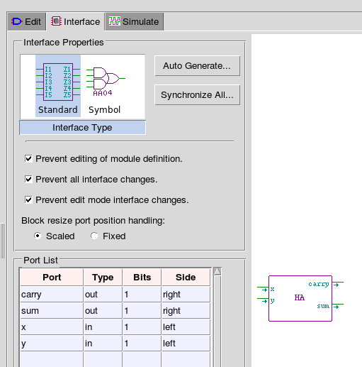
- Click on the Interface tab, and select your module (resize if you wish to make the name fit)
- Double click on your module to open the Interface Properties menu
- Add input ports on the left hand side, x and y
- Remember these names, you will need them when creating the module logic.
- The names must match exactly later, they are input parameters.
- Add two output ports on the right side, sum and carry.
- Remember these names, you will need them when creating the module logic.
- The names must match exactly later, they are output parameters.
- You can resize and move the ports on the image on the right.
- I would build my half adder module with the carry output as the upper output on the right side and the sum on the bottom.
-
- Return to the Edit tab and create an instance of your new module
- Right Click-> components -> modules -> Module Instance -> (select your module)
- Right click on your module and select open
- This will give you a blank screen, you are now editing your module.
- Add two inputs
- Right Click -> components -> modules -> module input
- Label the first x, the second y.
- Note, these must match the input names you gave when creating the interface.
- Add two output
- Right Click -> components -> modules -> module output
- Label the first sum and the second carry
- Note, these must match the output names you gave when creating the interface.
- Add a xor and and gate.
-
- Wire the circuit
-
- Right click anywhere on the blank canvas and select close
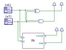
- Wire your module in and test it. The module and the circuit should produce the same output.
-
- After your module is working correctly, return to the Interface tab and lock editing the module interface and definition.
- Create a Full Adder
- Unlike a half adder, a full adder takes two bits, and a carry from the previous computation.
- Remember, the full adder takes three inputs and produces two outputs.
- By hand, add 23756 + 97289, using the addition algorithm. Write down the carry at each stage. (Yes, I mean on paper with a pen/pencil, or go to the white board and do this as a group)
- Note how the carry "ripples" through the computation.
- By hand add the binary numbers 01011 + 01101 using the same algorithm. Write down the carry at each stage.
- Note the initial carry is 0 in both cases.
- Note in both cases, we have three inputs to the adder for each addition step.
- I don't need this paper, it is so you see how a ripple carry adder works.
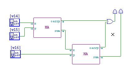
- A full adder is built from two half adders.
-
- At the gate level it would be
-
- carryOut = carryIn ·(x⊕y) + (xy)
- sum = (x ⊕ y ) ⊕ carryIn
- Derive a truth table for the full adder.
- The input will be x,y, carryIn
- The output will be sum, carryOut
- Place this in your circuit design as a comment.
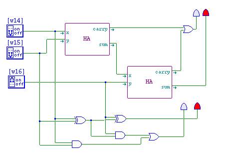
- Build a full adder in two ways
- At the gate level using and, or, not , xor
- Using your half adder module and other logic needed.
- Test your full adders.
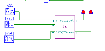
- Build a module to implement a full adder.
- The inputs should be x,y,carryIn (top to bottom)
- The outputs should be carryOut, sum (top to bottom)
- Build a circuit to test your new module
-
- Once the module is working, lock the interface.
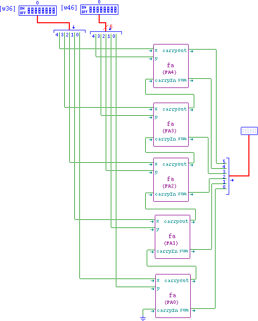
- Build a 5 bit ripple carry adder.
- Read the instructions first and LOOK AT THE CIRCUIT BELOW FOR THE FINAL LAYOUT
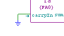
- This will consist of five full adders (FA0 through FA4)
- 10 inputs
- x0 through x4, the bits of the first number
- y0 through y4, the bits of the second number
- 6 outputs
- sum0 through sum4
- sumn is the sum of bits xn, yn and carryOutn-1
- For sum0, carryIn is 0
- carryOut, this is the carry out from FA4
- Build the ripple carry adder circuit
- Arrange five full adder circuits vertically.
- Connect a ground to carryIn from FA0
- The ground is components->I/O->ground
-
- Connect carryOutn to carryInn+1
- Create two DIP switches, and set the port width to be 5.
- components->I/O->DIP switch
- Double click on the switch
- Click on Port
- Change Bits to 5
-

- I would copy and paste for the second switch.
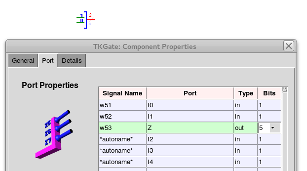
- Create two concat components, make the Z port 5 bits and add three more ports like I0.
- A concat component allows us to split a n bit wire into n 1 bit wires.
- The default is a 2 bit wide wire. But we need a 5 bit wide wire split from the DIP switches above.
- Get a concat component, components->I/O->concat
- Double click to bring up the component properties dialog
- click on I0, then click on Add three times
- Click on Z, and change the bit width to 5.
-
- Connect xn, yn to the corresponding ports on FAn
- Create an 6 bit LED bar
- Create a concat component, make the Z port 6 bits and add four more ports like I0
- Wire your ripple carry adder as shown
- Test your circuit to see that it works.
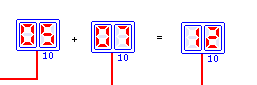
- Using Decimal based 7-Segment LEDs and comments to display your computations as shown below.
-
- Email a copy of the final circuit (a 5 bit ripple carry adder) to your instructor.

