Hardware Timers
Notes
- This comes from several places.
- A great article on timer interrupts
- The ATmega832P datasheet.
- A hardware timer is a part of most processors
- It does not use the cpu
- It has a register that is incremented every clock tick.
- A timer consists of
- A counter register, in this case either 8 bit or 16 bit
- See, for example the 74293
- This is driven by a clock either internal or external
- There is generally a prescaler
- The clock runs too fast for useful counting
- So the hardware provides the ability to scale the clock
- Ie count every 8, 64, 156 or 1204 ticks (in this case)
- A set of configuration registers
- A set of comparitors
- Depending on the configuration the timer will eventually trigger an interrupt
- When the counter reaches a set value
- When the counter overflows
- Then the counter is usually reset to 0.
- A counter register, in this case either 8 bit or 16 bit
- Timers are used for
- Delay ie the function delay uses timer 0.
- Watchdog Timers
- Timesharing
- We will look at timer 1, the 16 bit timer.
- Setting up the timer and roles
- The
cliandseiroutines- macros
- Set a bit in a control register
- cli - clear enable interrupts
- sei - set enable interrupts
- Basically, we want to turn interrupts off while messing with the timer registers.
- We might want to do this at other times as well, like in an interrupt.
- Everything after this is in the form XXXnX
- TCNT1
- Since there are three timers, TCNT0, TCNT1, TCNT2
- Sometimes there is also an A and a B register
- TCC1A, TCC1B
- TCNT1 is the value of the counter.
- The timer starts out at 0
- Some programs mess with this, others do not.
-
TCNT = 0;- TCNT is a macro to access this register.
- TCCRnA, TCCRnB are the timer counter control registers
-
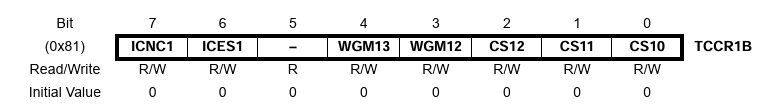 , from the ATmega328p Datasheet
- Bits CS10, 11 and 12 of TCCR1B are used to control the clock and clock scaling
- (1 << CS12) - sets the bit.
-
CS12 CS11 CS10 Result 0 0 0 No Clock 0 0 1 Clock/1 0 1 0 Clock/8 0 1 1 Clock/64 1 0 0 Clock/256 1 0 1 Clock/1024 1 1 0 External Clock, T1, falling Edge 1 1 1 External Clock, T1, raising Edge - CS12, CS11, CS10 constants.
-
TCCR1B |= (1 << CS12) | (0 << CS11) | (1 << CS10); - This sets bits CS12 and CS10 to be 1, or divide the clock by 1024
- TCCR1B bits WGM12 is used to control the waveform generated by the timer.
- This sets WGM12 (or the waveform bit) to be CTC or clear timer on compare match mode.
-
TCCR1B |= (1 << WGM12);
-
- OCR1A is the output control register.
- This is the value we want to compare the timer register to to call the interrupt.
- The clock runs at 16MHz or 16,000,000 ticks per second
- So the tick of the clock is 1/16,000,000 = 6.25x10⁻⁸ sec
- Or 63x10-9 seconds.
- 1ns = 1x10⁻⁹ seconds.
- So each clock pulse is about 63ns
- If we set the divider to be 1024,
- We change the timer every 1024 clock pulses or
- 1024 * 63 ns = every 64 μs
- So we get 1s/64x10-6 s = 15625 pulses per second
- If we want a 1 second timer, set OCR1A to be 15625
- Remember, this is an 16 bit timer, so the values are between 0 and 216 (65536)
-
OCR1A = 15623;
- TMSK1 an interrupt control register.
- If OCIE1A is set, this will cause an interrupt when the counter reaches the set value.
- This sets it so TIMER1_COMPA_vec will be called.
-
TIMSK1 |= (1 << OCIE1A)
- If OCIE1A is set, this will cause an interrupt when the counter reaches the set value.
- Finally, declare code for the interrupt vector
-
volatile bool ledA_state = LOW;

ISR(TIMER1_COMPA_vect) {
  ledA_state = !ledA_state;
  digitalWrite(GREEN, ledA_state);
}
-
- The