Adding Control of the View Volume
- We continue with This demo
- But Dalton Sevier, a student produced a Much better demo in 2024.
- Right hand vs Left Hand
- We generally use coordinate systems that observe the right hand rule
- In other words, we were looking along the negative z axis
- The right hand rule tells us how to orient in three space.
- Your author says
- "if you point the thumb of your right hand in the direction of the positive z-axis, then when you curl the fingers of that hand, they will curl in the direction from the positive x-axis towards the positive y-axis."
- "Another way to think about it is that if you curl the figures of your right hand from the positive x to the positive y-axis, then your thumb will point in the direction of the positive z-axis."
- "The default OpenGL coordinate system (which, again, is hardly ever used) is a left-handed system."
- In OpenGL, everything is drawn from the standard view volume.
- This is a cube from (-1, -1, -1) to (1,1,1)
- Everything is clipped
- Then everything is projected to 2D Normalized Device Coordinates.
- Finally that is mapped to Device Coordinates.
- That if we clipped in the front became the view frustum.
- And we frequently add a rear clipping plane.
- The derivation of this is not too bad, but probably outside what we want to do today.
- OpenGL Projection Matrix by Song Ho Ahn is a nice article on this.
- The Perspecitve and Orthographic Projection Matrix by Scratchpixel
- The distance to the near and far clipping planes.
- The coordinates of the top and bottom edges of the near plane.
- The coordinates of the left and right edges of the near plane.
-
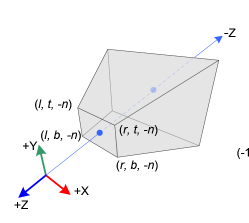 (source unknown)
- Generally we assume
- The camera is at (0,0,0) looking down the negative z axis.
- The positive y axis is up.
- The positive x axis is to the right.
- In 3D NDC this is backwards
- The camera is looking along the positive Z axis.
- So part of the transformation flips the axis.
- $ \begin{bmatrix} \frac{2*n}{r-l} & 0 & \frac{r+l}{r-l} & 0 \\ 0 & \frac{2*n}{t-b} & \frac{t+b}{t-b} & 0 \\ 0 & 0 & -\frac{f+n}{f-n} & \frac{-2fn}{f-n} \\ 0 & 0 & -1 & 0 \end{bmatrix}$
- And relized in
    Frustum(l,r,b,t,n,f) {
       var m =  mat4(1);
       m[0][0] = 2 * n / (r - l);
       m[0][1] = 0;
       m[0][2] = (r + l) / (r - l);
       m[0][3] = 0;

       m[1][0] = 0;
       m[1][1] = 2 * n / (t - b);
       m[1][2] = (t + b) / (t - b);
       m[1][3] = 0;

       m[2][0] = 0;
       m[2][1] = 0;
       m[2][2] = -(f + n) / (f - n);
       m[2][3] = -2 * f * n / (f - n);

       m[3][0] = 0;
       m[3][1] = 0;
       m[3][2] = -1;
       m[3][3] = 0;

       return m;
    }
- This is specified by the angle from top to bottom that is visible.
-
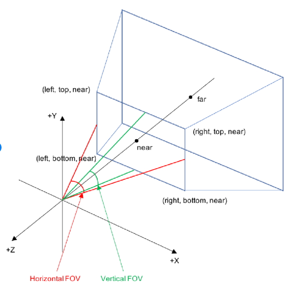 (source unknown)
- You also specify an aspect ratio
- And a near and far plane.
- Again the derivation is not bad.
- MV.js has code to produce this matrix.
- It is often useful to place the camera in modeling coordinates.
- Then transform everything from modeling coordinates to viewing coordinates.
- The camera is specified by three vectors
- Eye is the origin for the camera
- Look at is a vector from the origin of the camera to where it eye is focused
- UP is a vector pointing up for the camera.
- With the three of these, a transformation from modeling to viewing coordinates is possible.
- This is what they call a change of basis in linear algebra.
- And is accomplished with the
lookAtfunction in MV.js.
- Items in the model coordinate system are
- Transformed into the viewing coordinate system with the frustum transformation.
- The moved to Clipping space and projected to NDC space with the lookAt matrix.
-
var eye = lookAt([0,0,-1],[0,0,0],[0,1,0]);
var proj =  this.Frustum(-0.5,0.5,-0.5,0.5,1,20);
proj = mult(proj,eye);
this.gl.uniformMatrix4fv(this.projLoc, false,flatten(proj));