$\require{cancel}$
Intro To Graphics (Proper)
Give Section 1.1 of your book a read.
A pixel is a PI cture EL ement.
This is the smallest addressable element of a raster display.
Raster graphics are graphics based on stored pixels.
Ok, that is circular.
A bit of history
We started with screens covered with phosphor.
When an electron beam hit the phosphor, the screen would glow at that point.
Phosphor glows for a bit then fades
So it needs to be refreshed. (This will be important in a minute)
We have some choices with phosphor
Originally it just glowed or not, monochrome.
Later we decided we could shoot different intensities of electrons (I hope there are no physics majors in the room) for different shades of gray. (Grayscale)
Finally, we could add three different types of phosphor and get colors (RGB)
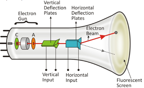
In a crt
The front is coated with phosphor or some other Florescent material.
An electron gun would produce a stream of electrons
Deflectors would change where the gun "hit" the screen.
This could trace any pattern on the screen.
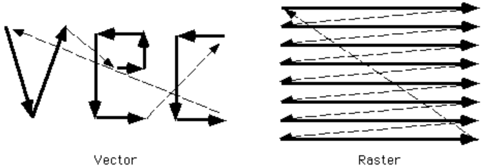
Vector graphics vs Raster Graphics
Again, raster graphics are presented as a set of dots.
Vector graphics where we store the vectors, or strokes
Think lineTo(), arcTo() ...
We work with vectors all the time,
You draw your letters that way.
You paint that way,
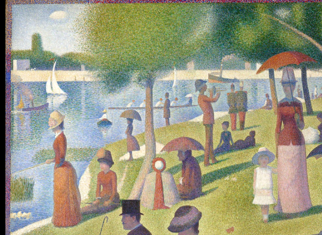
Unless you are Georges Seurat
But storage becomes an issue
A complicated image might involve many different primitives.
And storing these primitives will involve different data structures.
We would need to store these primitives to refresh the screen as it fades.
And we need to train the electron gun to perform each of these movements.
The solution, Raster graphics
We have the gun trace out a regular pattern
We put a screen so we only hit the phosphor at designated areas.
We have the gun read the values to "fire" from a table.
This table eventually becomes the frame buffer .
This means that
We need to convert vectors to dots in the frame buffer.
This is known as rasterization.
We will study multiple rasterization techniques.
The equivalent is storing images.
The NetPBM format is nice for demonstrating this
It is very old and probably not used very much.
But here is a demo.
Another item might be this file , a map of the US saved as a scalable vector graphics (svg) file.
I have a program that edits this file to produce This map
Vector vs Raster
Vector is continuous
This means you can scale at will.
But irregular memory/storage
Display/redisplay time related to number of objects and not uniform.
Filled areas problematic.
Raster is discrete
Known storage and redisplay time.
No problem filling in areas.
Jaggies,
here is a raster vs vector scaling demo
By the way
Memory was/is expensive
And originally would not fit onto the "chip"
So a frame buffer is part of a graphics card. (Or other device)
This is a giant array, the size of the screen (or resolution) supported
One bit for monochrome
Multiple bits for greyscale and color.
The first commercial frame buffer
had resolution 512x512
8 bits per pixel (greyscale)
$15,000 (and you thought you paid too much for your graphics card)
A 32 bit color frame buffer
Generally supports 8 bit color for red, green and blue
And 8 bits for color.
So a 1280x1024x32 bit display has about 6MB of memory in the frame buffer.
Eventually memory became inexpensive enough that we could
Double the size of the frame buffer.
Use 1/2 for displaying the current image
Use 1/2 for drawing the next image.
This is called double buffering.
Simple graphics cards had algorithms to rasterize simple 2d primitives.
Later we added the ability to rasterize 3d primitives.
We will discuss these techniques soon.
Most modern displays are still based on these ideas
There is a grid of
Liquid crystal "elements"
leds
Some other method of producing various intensitis of red, green and blue.
 (From https://www.learnersplanet.com/worksheets-printables/how-does-crt-television-work)
 (Hallmark)
 (From wikipedia)
 (https://www.cs.uic.edu/~jbell/CourseNotes/ComputerGraphics/VectorVsRaster.html")