Flip Flops
Notes
- A flip-flop is a device that only changes when a "clock" goes from low to high.
- This is what gives us the control to accomplish many tasks in a cpu
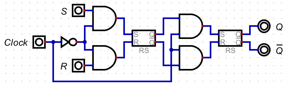
- The rs-flipflp
- Input: R,S and a clock
- Output: Q, Q
- When the clock goes from low to high, the input of either r or s will be stored.
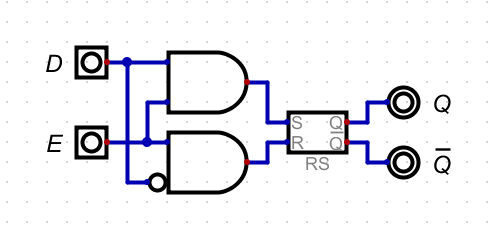
- The D flip flop is really the base component we will use.
- Input
- Output: Q and Q
- When the clock changes from low to high, the value of D is stored in the circuit.
- Either of these can built with a leader-follower (formerly master-slave) configuration
- The idea is that we use 2 latches in series with a clock.
- When the clock is 0, a value can be stored in the first latch
- When the clock goes to 1, the value of the first latch is transferred to the second latch.
- But the and gates at before the first latch keep it from changing
- So the first latch can only be changed when the clock is low (user input)
- And the second latch can only be changed when the clock is high (latch input)
-
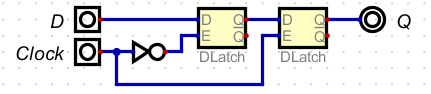
- This works for the D Flip-Flop as well
- Digital does not seem to have a D latch, so I made one
-
- Then the flip-flop
-
- There are other flip-flops
- The J-K flip-flop eliminates the invalid 1-1 state of the R-S Flip-flop.
- 1-1 means toggle the value
- The T flip-flop toggles the state.
- There are versions of the flip-flops that have pre and clear lines
- When pre is 0, the value is set to 1 regardless of the clock
- When clr is 0, the value is set to 0 regardless of the clock
- Digital's version uses set and clr, (not inverted)
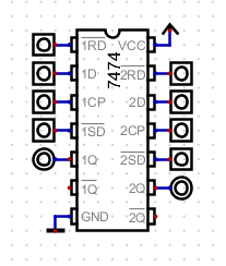
- There are numerious flip-flops available in the 74xxx series.
- The 74LS74
- Datasheet
- Contains 2 D flip-flops
- It has a clr and pre line per flip-fllop
- As well as a clock and data line per flip flop.
-
- FlipFlops.dig