The ALU for the 8 bit computer.
Notes
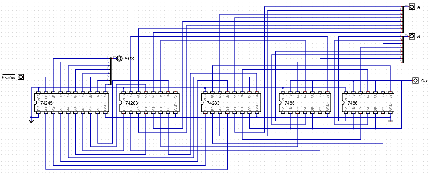
- The Diagram
- Parts
- 74x245 - tri-state device to control data to the bus
- 74x283 - 4 bit adder
- 4 A inputs
- 4 B inputs
- A carry in
- 4 sum outputs
- 1 carry out output
- 74x86 - xor gate
- 4 a inputs
- 4 b inputs
- 4 a ⊕ b outputs
-
- I had troubles remembering so
- If su is 0, the b bit is preserved
- If su is 1, the b bit is flipped
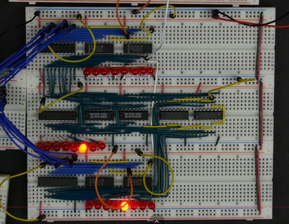
- Building the Circuit
- He has an input of A and B (wired directly to the registers.
- He has an input of su, which he runs through the xor gates with the values from b.
- He wires the outputs of b ⊕ su to the b inputs of the adders
- He wires a to the inputs of the adders.
- He wires the outputs of the adders to the tristate
-
-
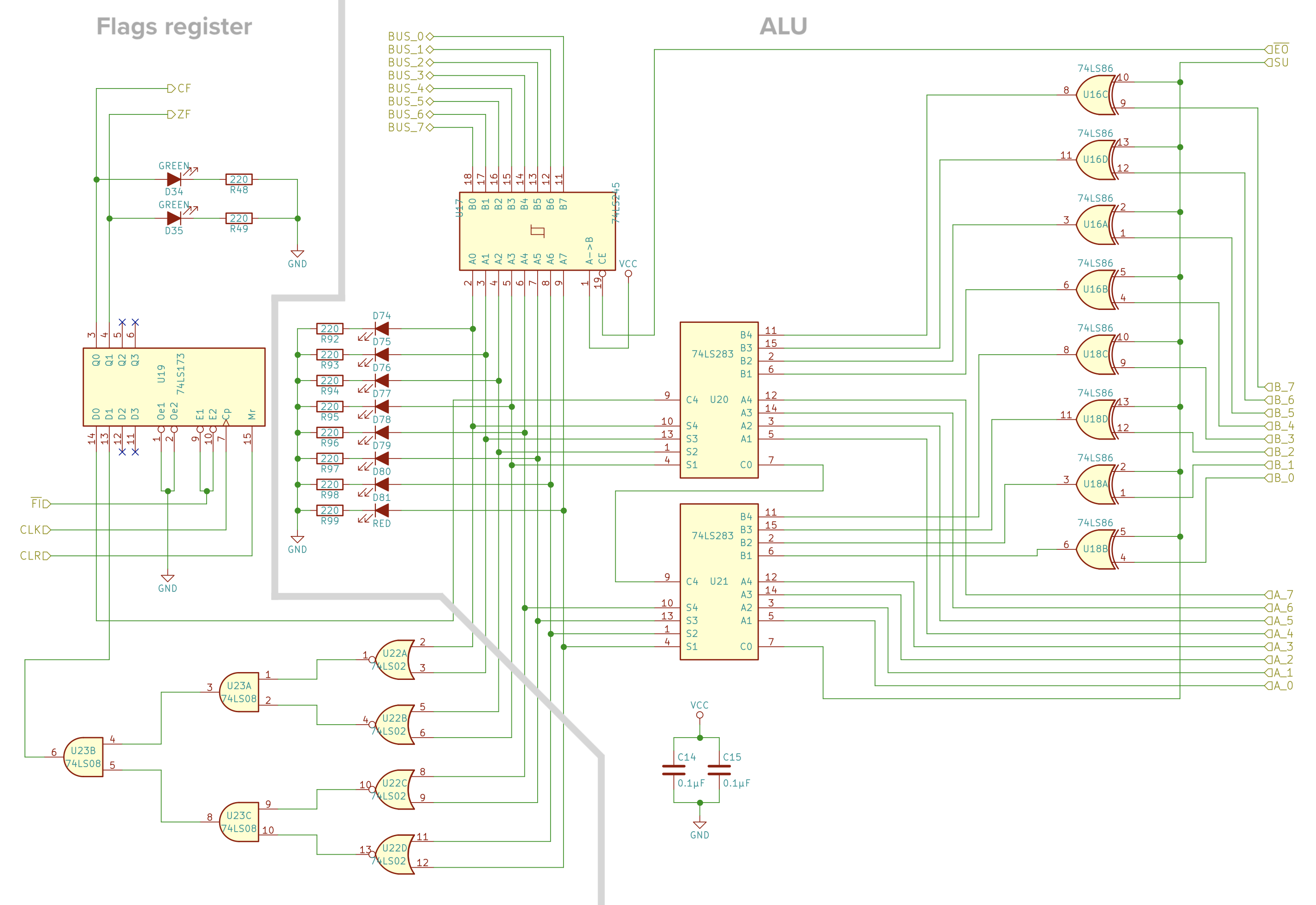
- The Digital File
- There is also a flags register located on this breadboard
- It includes the carry_out from the second adder
- And a circuit to compute the zero of the addition.