Memory and PC for the 8 bit computer
Objectives
Notes
- Memory
- Documentation
- The 8 bit computer has a word size of 8 bits.
- Therefore memory must be 8 bits wide
- It has a 4 bit address, so 16 words tall
- A total of 16x8 = 128 bits.
- Ben uses the 74x189 chip
- This is a 64 bit ram
- 4 Output lines (Q 0-3) for a 4 bit word.
- 3 address lines (A 1-3) for 16 words.
- 4 data lines (D 0-3)
- cs, chip select
- we, write enable
- This memory is strange in that the output is inverted.
- So he uses two 74x04 , 6 input inverters, to fix this.
- The 74x1157 is a 4 bit wide 2 to 1 MUX
- A (1-4) and B (1-4) are inputs
- Y (1-4) is selected output
- S is select between A and B
- G is an enable (on low) line
- His address input is either a 4 bit register, loaded from the bus (74x173) or a 4 position dip switch.
- He uses a mux to select between them.
-

- His data input is also either the 8 bits from the bus or an 8 position dip switch.
- He uses two muxes to select between them.
-

- I took a picture before he added a save button to the left of the data entry dip switches
- I built a digital circuit for this, but it was a mess too!
- You can see this in action at about 3:00 in This video
- Yes, he enters his program by hand, enter address, enter code, press save.
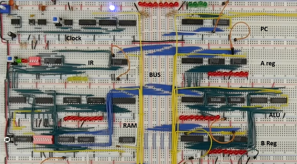
- The PC is here
- And is mostly what you would expect.
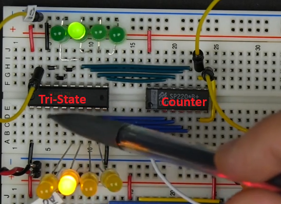
- A tri-state device to control access to the bus
- A 74x161 binary counter.
- Four data in lines
- Five data out lines (carry out of bit 4)
- A clock
- A clear
- A Load
- If load is low, it loads data from data in on clock pulse
- Otherwise it increments on clock pulse
- An enable line.
-

- Implementing this is not too bad.
- Count to 16 in four bit binary.
- Note that the first bit flips every other time
- What will this circuit do?

- That leads to this circuit
-

- The digital file for counters.
-
- Only 4 bits are sent to the bus
- The top four are 0.
- Note this will also receive data from the bus for jump commands
-