$\require{cancel}$
Physical Circuits.
- I will build some physical circuits for you.
- If you wish, there is some equipment in Ross 129, you may use this.
- Please see me first.
- We will be building on a "bread board"
-
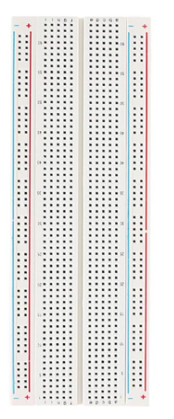
- The line down the middle divides this into two parts.
- And is generally just right for a chip to span.
- On the sides are two wires connected the length of the board.
- They are intended for power.
- Plug a wire from the positive into the red row.
- Plug a wire from the ground into the blue row.
- Then jump from these to wires on the board to power a chip.
- In the middle, the five holes in a row are connected to a common wire.
-
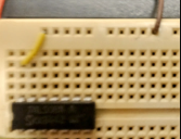
- This is just a little different from the above.
- But the brown wire at the top is the positive voltage supply
- The yellow wire brings this down to the column
- And the chip's top left pin is plugged into the positive.
- Chips generally have
- A Vcc or voltage input pin.
- A GND or ground pin.
- A number of input/output pins based on the circuit
- For a given chip, you can get the Data Sheet
- This usually shows
- The physical layout.
- The logic diagram.
- The actual schematics
- Operating Characteristics.
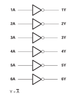
- Let's look at the 74LS04N, a HEX Inverter
- The datasheet
- There is a chip view
-
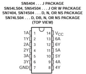
- Note the indentation at the top, so you can identify the pins
- Note the labels on the pins
- There is a logical view
- And a bunch of other information.
- Look at the operation of the 7404 on the digital trainer.